


Maintenir votre monde à jour et opérationnel®

Keeping Your World Up & Running®
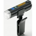
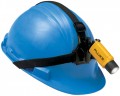
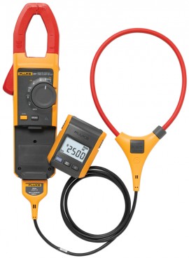
Permet à une personne d'effectuer un travail qui prendrait normalement deux personnes avec l'affichage amovible. Cet affichage distant v.e.v. c.a./c.c. permet à l'utilisateur d'entourer un conducteur pour mesurer le courant. De plus, l'utilisateur peut se diriger vers les commandes électriques ou retirer l'équipement de protection tout en visualisant des lectures en temps réel.
Permet à une personne d'effectuer un travail qui prendrait normalement deux personnes avec l'affichage amovible. Cet affichage distant v.e.v. c.a./c.c. permet à l'utilisateur d'entourer un conducteur pour mesurer le courant. De plus, l'utilisateur peut se diriger vers les commandes électriques ou retirer l'équipement de protection tout en visualisant des lectures en temps réel.
Une seule personne aujourd'hui pour effectuer le travail de deux auparavant
Permets à un technicien de faire le travail qui autrement nécessiterait deux personnes. Cet affichage à distance permet à l'utilisateur de fixer un conducteur et de détacher l'affichage. En outre, ils peuvent traverser la pièce pour configurer les commandes ou retirer l'équipement de protection, tout en regardant des lectures en temps réel.
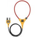
La sonde de courant souple iFlex® (incluse) élargit la gamme de mesure jusqu’à 2500 A c.a. tout en offrant une plus grande flexibilité d’affichage. Avec son cordon de près de 2 m, vous pouvez désormais mesurer les espaces exigus, les conducteurs de taille importante et les câbles désorganisés.
Capacité de mesure
Caractéristiques
“RMS” stands for root-mean-square. It comes from a mathematical formula that calculates the “effective” value (or heating value) of any ac wave shape. In electrical terms, the ac rms value is equivalent to the dc heating value of a particular waveform—voltage or current. For example, if a resistive heating element in an electric furnace is rated at 15 kilowatts (kW) of heat at 240 V ac rms, then we would get the same amount of heat if we applied 240 V of dc instead of ac.
Electrical power system components such as fuses, bus bars, conductors, and thermal elements of circuit breakers are rated in rms current because their main limitation has to do with heat dissipation. If we want to check an electrical circuit for overloading, we need to measure the rms current and compare the measured value to the rated value for the component in question.
If a current clamp is labeled and specified to respond to the true-rms value of current, it means that the clamp’s internal circuit calculates the heating value according to the rms formula. This method will give the correct heating value regardless of the current wave shape.
Certain low-cost current clamps, which don’t have true rms circuitry, use a short cut method to find the rms value.
These meters are specified to be “average responding-rms indicating.” These meters capture the rectified average of an ac waveform and scale the number by 1.1 to calculate the rms value. In other words, the value they display is not a true value, but rather is a calculated value based on an assumption about the wave shape. The average responding method works for pure sine waves but can lead to large reading errors up to 40 percent, when a waveform is distorted by nonlinear loads such as adjustable speed drives or computers. The table below gives some examples of the way the two different types of meters respond to different wave shapes.
Some true-rms clamp meters are ac coupled, which gives the rms value of only the ac component of a waveform. (This dates from the time when a majority of measurements in the electrical industry were predominately sinusoidal with no dc offset.) To measure the rms with an ac coupled clamp meter, first measure the rms value of the ac component. Then measure the waveform on the dc scale. Combine the ac and dc components by squaring each, adding the results, and then extracting the square root. The function AC+DC in Fluke true rms clamp meters essentially does the calculation for you.
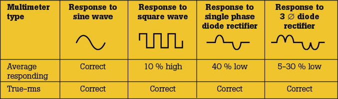
A comparison of average responding and true-rms units
En savoir plus sur la v.e.v.Présentement disponible en anglais seulement
Présentement disponible en anglais seulement
| Courant alternatif via pince | |
| Gamme | 999.9 A |
| Résolution | 0.1 A |
| Précision | 2% ±5 chiffres (10 à 100 Hz) 5% ±5 chiffres (100 à 500 Hz) |
| Facteur de crête (50/60 Hz) | 3 à 500 A 2.5 à 600 A 1.42 à 1000 A Ajouter 2% pour FC > 2 |
| Courant c.a. via sonde de courant souple | |
| Gamme | 999.9 A, 2500 A, 45 à 500 Hz |
| Résolution | 0.1, 1 A |
| Précision | 3% ±5 chiffres |
| Facteur de crête (50/60 Hz) | 3 à 1100 A 2.5 à 1400 A 1.42 à 2500 A Ajouter 2% pour FC > 2 |
| Courant c.c. | |
| Gamme | 999.9 A |
| Résolution | 0.1 A |
| Précision | 2% ±5 chiffres |
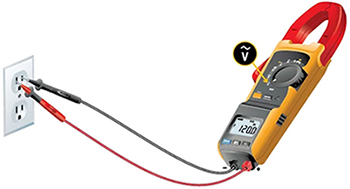
| Tension c.a. | |
| Gamme | 600 , 1000 V |
| Résolution | 0.1, 1 V |
| Précision | 1.5% ±5 chiffres (20 à 500 Hz) |
| Tension c.c. | |
| Gamme | 600 , 1000 V |
| Résolution | 0.1, 1 V |
| Précision | 1% ±5 chiffres |
Cliquer sur une catégorie pour voir une sélection d'accessoires compatible avec le Fluke 381 Pince multimètre à affichage distant v.e.v. c.a./c.c. avec iFlex.


| Courant alternatif via pince | |
| Gamme | 999.9 A |
| Résolution | 0.1 A |
| Précision | 2% ±5 chiffres (10 à 100 Hz) 5% ±5 chiffres (100 à 500 Hz) |
| Facteur de crête (50/60 Hz) | 3 à 500 A 2.5 à 600 A 1.42 à 1000 A Ajouter 2% pour FC > 2 |
| Courant c.a. via sonde de courant souple | |
| Gamme | 999.9 A, 2500 A, 45 à 500 Hz |
| Résolution | 0.1, 1 A |
| Précision | 3% ±5 chiffres |
| Facteur de crête (50/60 Hz) | 3 à 1100 A 2.5 à 1400 A 1.42 à 2500 A Ajouter 2% pour FC > 2 |
| Courant c.c. | |
| Gamme | 999.9 A |
| Résolution | 0.1 A |
| Précision | 2% ±5 chiffres |
| Tension c.a. | |
| Gamme | 600 , 1000 V |
| Résolution | 0.1, 1 V |
| Précision | 1.5% ±5 chiffres (20 à 500 Hz) |
| Tension c.c. | |
| Gamme | 600 , 1000 V |
| Résolution | 0.1, 1 V |
| Précision | 1% ±5 chiffres |
Cliquer sur une catégorie pour voir une sélection d'accessoires compatible avec le Fluke 381 Pince multimètre à affichage distant v.e.v. c.a./c.c. avec iFlex.


 ).
). sur le Fluke 381.
 .
.
 .
. sur le Fluke 381) pour sélectionner les Hz.


