- Sign In
- |
- Sign Up
- |
- My Quote (0)
- |
- CART (0)


Energy & Power Measurement Solutions
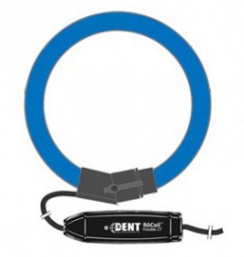
24in RoCoil mV Flexible (Rogowski) Current Transformers. 40 to 10,000A.
24in RoCoil mV Flexible (Rogowski) Current Transformers. 40 to 10,000A.
Discontinued!
This product has been discontinued and is no longer available.
This is the direct replacement:
Like its name implies, the RoCoil mV produces a millivolt output for use with power meters without a built-in amplifier/integrator circuitry. These CTs are available in standard lengths up to 72" and current ranges up to 6000A AC. The RoCoil mV requires 5-24V DC for operation, which can be supplied from a Line-Powered ELITEpro or optional external power supply.
Standard Features:

| Dimensions | RMV-16 | RMV-24 | RMV-36 | RMV-72 |
|---|---|---|---|---|
| A - Window Size | 13 cm(5") | 19 cm(7") | 26 cm(10") | 56 cm(22") |
| B - Transformer Coil O.D. | 15 cm(6") | 21 cm(8") | 29 cm(11") | 58 cm(23") |
| C - Transformer Length | 40 cm(16") | 60 cm(24") | 90 cm(36") | 180 cm(72") |
| D - Locking ConnectorO.D. | 3.6 cm(1.4") | |||
| E - Transformer Coil Diameter | 1.5 cm(0.6") | |||
| F - Wire Lead Total Length | 2m(80") | |||
| G - Length of mV Module | 9.5 cm (3.8") | |||
| H - Width of mV Module | 3.2 cm (1.3") | |||
| Four Lengths | 40 cm (16"), 60 cm (24"), 90 cm (36"), 180 cm (72") |
| 4 Window Sizes | 13 cm (5"), 19 cm (7"), 26 cm (10"), 52 cm (20") |
| 4 Current Ranges* | 16", 1000A, 10-1300A AC 24", 2000A, 30-2600A AC 36", 3000A, 30-3900A AC 72", 6000A, 60-6000A AC |
| Output Signal | 333 mV AC at rated current Max output 1,665 mVAC |
| Accuracy | < 1% typical at 2% to 500% of rated current |
*Depending on meter compatibility. See ELITEpro™ and PowerScout™ specifications for details.
All accuracies specified at 20°C (±2°C)with RoCoil mV™ centered on conductor.
| Output Signal | (16") 333 mV @ 1000A (24") 333 mV @ 2000A (36") 333 mV @ 3000A (72") 333 mV @ 6000A |
1665 mV @ 5000A 999 mV @ 6000A 666 mV @ 6000A |
| Max Output | 1.66VAC | |
| Power Requirement | 5-24 VDC, 30 mA Maximum | |
| Wire Color | Red = Power (+) Black = Power (-) White = Signal (+) Green = Signal (-) |
|
| Phasing | Arrow Points Towards Load | |
| Phase Shift | < 1° at rated current | |
| Frequency Range | 45-600 Hz | |
| Linearity | ± 0.2% | |
| Conductor Position Sensitivity | ± 2% maximum | |
| Influence of External Field | ± 1.5% maximum | |
| Temperature Sensitivity | 0.07% per °C | |
| Coil Materials | Blue thermoplastic rubber, flame retardant UL 94 V-0 rated |
| Coupling Materials | Polypropylene UL 94 V?0 rated |
| Case Material | ABS UL 94 V-0 rated |
| Shielding | 85% transducer, 100% output lead |
| Working Temp | -20 °C to +60 °C (-4° to +140 °F) |
| Working Voltage | 600 Vrms maximum |
| Dielectric Strength | 7400 VAC around coil 600 VAC rated leads |
| Certifications | Conforms to UL STD61010?1 Certi?ed to CAN/CSA STDC22.2 No. 61010 |
One of the most frequently asked questions in our tech support department is this: "Can I get CTs with longer leads or extend the leads myself? What's the maximum length for CT leads?".
Standard lead length for a DENT current transformer is 3 meters (with a 7 meter option available for some models). Occasionally, because of electrical room layout or other factors, there is a requirement for longer leads on a current transformer. Therefore, extending the CT leads is necessary. The following is a brief overview of options for extending CT leads based on CT type. Note that the length recommendations listed below apply to PowerScout Series and ELITEpro XC instruments ONLY. To extend RoCoil leads for use with the TCA-5, please contact our experts to get advice specific to your application.

Split-Core Current Transformers leads can be extended up to 500 feet using extensions of the same wire type/AWG.
600 V Rated VW-1, 105°C, 20 AWG, black and white twisted pair, cURus
Sure-Connect sealed butt splices which require a crimping tool and hot air gun. Always follow manufacturer's instructions.

RoCoil CT leads can be extended up to 100 feet using extensions of the same wire type/AWG.
"Bare" RoCoil: Shielded cable with thermoplastic insulation, 1000 V AC VW-1, 2 x 26 AWG, 80°C, cURus
Sure-Connect sealed butt splices which require a crimping tool and hot air gun. Always follow manufacturer's instructions.

Solid Core (Toroid) CT leads can be extended up to 500 feet using extensions of the same wire type/AWG.
UL1015 24 AWG 7 Strand Black & White Twisted Pair (1 twist per inch), 600 V rated
Sure-Connect sealed butt splices which require a crimping tool and hot air gun. Always follow manufacturer's instructions.

Rogowski coil, named after Walter Rogowski, is an electrical device for measuring alternating current (AC) or high-speed current pulses. It consists of a helical coil of wire with the lead from one end returning through the center of the coil to the other end so that both terminals are at the same end of the coil. The whole assembly is then wrapped around the straight conductor whose current is to be measured.
Since the voltage that is induced in the coil is proportional to the rate of change of current in the straight conductor the output of the Rogowski coil is usually connected to an electrical (or electronic) integrator circuit in order to provide an output signal that is proportional to the current.
The relationship between voltage and rate of change of current is explained in the following equation where "V" is voltage and "M" is a constant:

Rogowski coil accuracy is usually calibrated with the conductor centered in the CT window. In practice, however, the CT typically hangs on the conductor which can introduce measurement errors. Note that the error is greatest when the CT connector hangs on the conductor. The following diagram outlines the error introduced simply by moving the conductor to different positions within the opening of the Rogowski coil.

Best practice for Rogowski coil installation is to center the conductor as best as conditions allow. In addition, it's a good idea to keep any other conductors (those you do not wish to measure) at a minimum distance of 2x the diameter of the Rogowski coil CT.
Also, keep in mind that although a Rogowski coil is ideal for large amperage loads, accuracy of the coil may be reduced on smaller loads (<20 A).
| Dimensions | RMV-16 | RMV-24 | RMV-36 | RMV-72 |
|---|---|---|---|---|
| A - Window Size | 13 cm(5") | 19 cm(7") | 26 cm(10") | 56 cm(22") |
| B - Transformer Coil O.D. | 15 cm(6") | 21 cm(8") | 29 cm(11") | 58 cm(23") |
| C - Transformer Length | 40 cm(16") | 60 cm(24") | 90 cm(36") | 180 cm(72") |
| D - Locking ConnectorO.D. | 3.6 cm(1.4") | |||
| E - Transformer Coil Diameter | 1.5 cm(0.6") | |||
| F - Wire Lead Total Length | 2m(80") | |||
| G - Length of mV Module | 9.5 cm (3.8") | |||
| H - Width of mV Module | 3.2 cm (1.3") | |||
| Four Lengths | 40 cm (16"), 60 cm (24"), 90 cm (36"), 180 cm (72") |
| 4 Window Sizes | 13 cm (5"), 19 cm (7"), 26 cm (10"), 52 cm (20") |
| 4 Current Ranges* | 16", 1000A, 10-1300A AC 24", 2000A, 30-2600A AC 36", 3000A, 30-3900A AC 72", 6000A, 60-6000A AC |
| Output Signal | 333 mV AC at rated current Max output 1,665 mVAC |
| Accuracy | < 1% typical at 2% to 500% of rated current |
*Depending on meter compatibility. See ELITEpro™ and PowerScout™ specifications for details.
All accuracies specified at 20°C (±2°C)with RoCoil mV™ centered on conductor.
| Output Signal | (16") 333 mV @ 1000A (24") 333 mV @ 2000A (36") 333 mV @ 3000A (72") 333 mV @ 6000A |
1665 mV @ 5000A 999 mV @ 6000A 666 mV @ 6000A |
| Max Output | 1.66VAC | |
| Power Requirement | 5-24 VDC, 30 mA Maximum | |
| Wire Color | Red = Power (+) Black = Power (-) White = Signal (+) Green = Signal (-) |
|
| Phasing | Arrow Points Towards Load | |
| Phase Shift | < 1° at rated current | |
| Frequency Range | 45-600 Hz | |
| Linearity | ± 0.2% | |
| Conductor Position Sensitivity | ± 2% maximum | |
| Influence of External Field | ± 1.5% maximum | |
| Temperature Sensitivity | 0.07% per °C | |
| Coil Materials | Blue thermoplastic rubber, flame retardant UL 94 V-0 rated |
| Coupling Materials | Polypropylene UL 94 V?0 rated |
| Case Material | ABS UL 94 V-0 rated |
| Shielding | 85% transducer, 100% output lead |
| Working Temp | -20 °C to +60 °C (-4° to +140 °F) |
| Working Voltage | 600 Vrms maximum |
| Dielectric Strength | 7400 VAC around coil 600 VAC rated leads |
| Certifications | Conforms to UL STD61010?1 Certi?ed to CAN/CSA STDC22.2 No. 61010 |
One of the most frequently asked questions in our tech support department is this: "Can I get CTs with longer leads or extend the leads myself? What's the maximum length for CT leads?".
Standard lead length for a DENT current transformer is 3 meters (with a 7 meter option available for some models). Occasionally, because of electrical room layout or other factors, there is a requirement for longer leads on a current transformer. Therefore, extending the CT leads is necessary. The following is a brief overview of options for extending CT leads based on CT type. Note that the length recommendations listed below apply to PowerScout Series and ELITEpro XC instruments ONLY. To extend RoCoil leads for use with the TCA-5, please contact our experts to get advice specific to your application.
Split-Core Current Transformers leads can be extended up to 500 feet using extensions of the same wire type/AWG.
600 V Rated VW-1, 105°C, 20 AWG, black and white twisted pair, cURus
Sure-Connect sealed butt splices which require a crimping tool and hot air gun. Always follow manufacturer's instructions.
RoCoil CT leads can be extended up to 100 feet using extensions of the same wire type/AWG.
"Bare" RoCoil: Shielded cable with thermoplastic insulation, 1000 V AC VW-1, 2 x 26 AWG, 80°C, cURus
Sure-Connect sealed butt splices which require a crimping tool and hot air gun. Always follow manufacturer's instructions.
Solid Core (Toroid) CT leads can be extended up to 500 feet using extensions of the same wire type/AWG.
UL1015 24 AWG 7 Strand Black & White Twisted Pair (1 twist per inch), 600 V rated
Sure-Connect sealed butt splices which require a crimping tool and hot air gun. Always follow manufacturer's instructions.
Rogowski coil, named after Walter Rogowski, is an electrical device for measuring alternating current (AC) or high-speed current pulses. It consists of a helical coil of wire with the lead from one end returning through the center of the coil to the other end so that both terminals are at the same end of the coil. The whole assembly is then wrapped around the straight conductor whose current is to be measured.
Since the voltage that is induced in the coil is proportional to the rate of change of current in the straight conductor the output of the Rogowski coil is usually connected to an electrical (or electronic) integrator circuit in order to provide an output signal that is proportional to the current.
The relationship between voltage and rate of change of current is explained in the following equation where "V" is voltage and "M" is a constant:
Rogowski coil accuracy is usually calibrated with the conductor centered in the CT window. In practice, however, the CT typically hangs on the conductor which can introduce measurement errors. Note that the error is greatest when the CT connector hangs on the conductor. The following diagram outlines the error introduced simply by moving the conductor to different positions within the opening of the Rogowski coil.
Best practice for Rogowski coil installation is to center the conductor as best as conditions allow. In addition, it's a good idea to keep any other conductors (those you do not wish to measure) at a minimum distance of 2x the diameter of the Rogowski coil CT.
Also, keep in mind that although a Rogowski coil is ideal for large amperage loads, accuracy of the coil may be reduced on smaller loads (<20 A).